


We're sharing our findings after spending some time building a new automated I3C test bench using the Scout SC4420 Serial Bus Controller by Signal Craft Technology. There's really a shortage of reviews of these types of devices as almost everyone using them is working on confidential / proprietary projects which cannot be discussed in an open forum. I've received numerous emails over the past few months from folks asking how to best get up and running with an I3C Controller, so I've decided to spend some time creating content on this topic. One of the most enjoyable aspects of my work with I3C is that I'm not bound by those constraints and can share my learnings openly in hopes that others working in the field will benefit. I have no affiliation with Signal Craft Technologies and received no incentive, financial or otherwise, to review their product. Let's get started with some brief background and then dive in to the hands on review.
What is it?
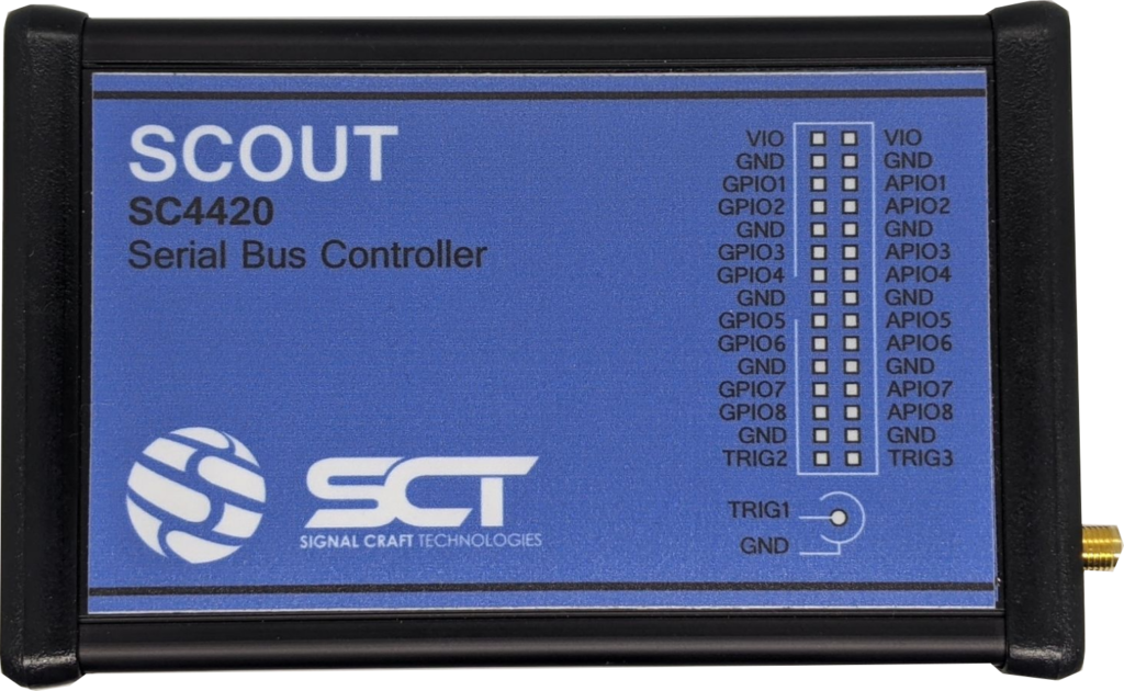
The Scout SC4420 is a Deterministic Serial Bus Controller (quite similar to a USB Host Adapter) that features support for several MIPI protocols, including I3C v1.1. The base product supports traditional SPI protocol capabilities, and RFFE, SPMI, and I3C protocols are made available via the purchase of optional feature licenses. It's important to call it the nuance implied by their use of the term 'deterministic'. Unlike traditional USB host adapters, where communication is handled by hardware peripherals and can have some variations in timing due to interrupt priority levels and other tasks currently being serviced by the microcontroller, the timing of a 'deterministic' controller is fixed and 100% repeatable. This is achieved by implementing the logic in hardware (FPGA) rather than using a sequential logic device such as microcontroller. Depending on the type of testing and development, this nuance may be quite important.
What are it's capabilities?
In short, the device can operate as an I3C Controller, up to 12.5MHz clock frequency, SDR and DDR support, with a bus voltage range from 0.8V to 3.3V. The device is accurately advertised and documented, although it does take a bit of digging to surface the important details, as the main product page only covers the high-level features. The product brief [PDF] is much better at painting the full picture of the device's capability. However, if you're looking to build an understanding of it's command interface and level of software support (spoiler alert, or lack thereof) you'll need to go even deeper and create an account to gain access to their support portal. There you'll be able to find the user manual which contains the necessary information to understand how to interact with the device. I definitely recommend reviewing this document prior to making a purchase as it will give you an idea of the learning curve to get up and running with this product.
How much does it cost?
The price of the product is not publicly posted on their website or online, and is only available by requesting a quotation. Respecting their process, I will not disclose the exact amount paid for the product, but for budgeting purposes the cost of the base product + MIPI-I3C feature unlock can be considered to be ~$1000 USD.
I was pleasantly surprised that the device was actually available to ship within just a few days after placing the order. Not having a long-lead time for a device like this is somewhat atypical given the supply chain constraints on FPGAs.
Where can it be purchased?
As of the time of writing, the only means of procuring this device is to purchase directly from Signal Craft Technologies. Better suited for enterprise sales, the purchase needs to go through the formal process of requesting a quote, issuing a purchase order, paying by bank transfer, and providing them with a shipping account. Regrettably they do not have an online store where the purchase can be made via credit card. They also do not work with any distributors, so there's no option to acquire this through Digikey, Mouser, or the other common test equipment vendors. Signal Craft Technologies ships the devices out from their office in Canada.
Alright, enough background, let's see it in real life...
Unboxing
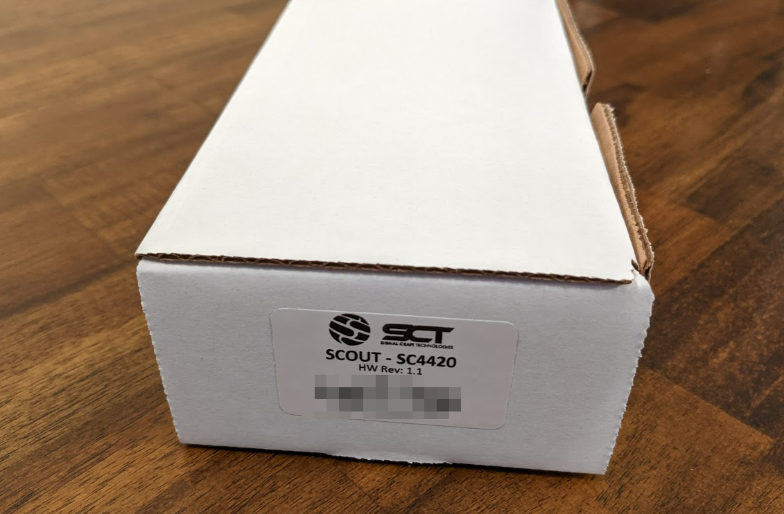
The device comes in a plain white box. The only marking is a label placed on the side with the product name and details, including the serial number. The box contains only the device and the connector used to mate with the device's external 5V DC supply input. The device itself comes in an ESD bag and is well-packed with foam end-caps.


It's worth noting that the device does not come with a USB cable or wire harness for the signals. This is clearly indicated in their documentation, however it's worth mentioning as a reminder to be sure to order those items ahead of time. I ordered this USB 2.0 A male to B male cable from a popular online bookstore. It appears that Signal Craft Technologies sells a wire harness separately, although the connector is a standard 0.1in/2.54mm pitch pin header, so it's possible to just use typical jumper cables. We've been using Qwiic connectors and harnesses on our test setup, so I opted to use this cable to connect the SC4420 to my I3C Target.


Teardown
Like many engineers, I cannot resist taking things apart and seeing how they are made. While a full breakdown and analysis of the electrical design is well beyond the scope of this review, it's worth sharing the highlights. The Scout SC4420 design is based on the Xilinx Zynq XC7Z010-series FPGA. This device and it's supporting components + power supplies make up the bulk of the system. Near the connectors there is some circuitry for input protection and interfacing the signals between the FPGA and the outside world.

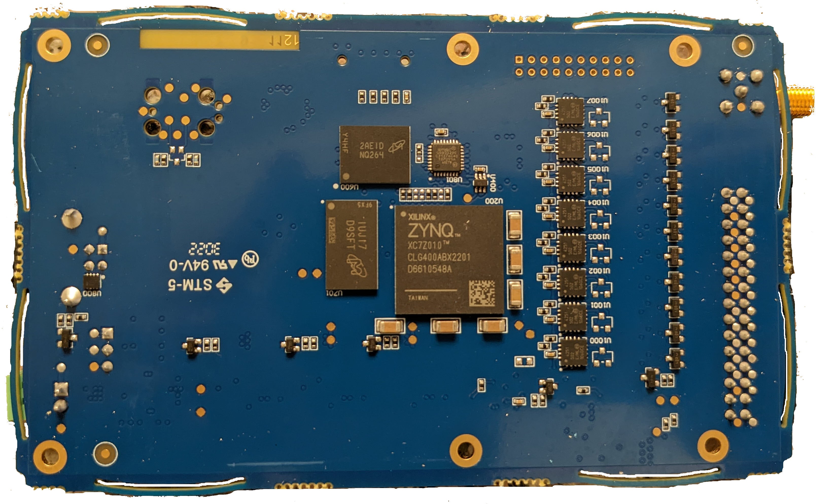
The PCB is a 12-layer board with well-organized component placements and an elegant layout. One particularly clever aspect of the design is the actual PCB outline. Each edge of the board features 2 x bowed cutouts which will be ever-so-slightly compressed when board is installed in the extruded aluminum enclosure. This is a fantastic way to ensure that the board isn't loose in the enclosure nor so tight that makes assembly a challenge. I really like this subtle design feature and look forward to the opportunity to try to implement in my own PCB design at some point in the future.


Plugging it in
After I put it all back together, it was time to power it on for the first time. An interesting curiosity about the device that isn't mentioned anywhere in the manual, and honestly gave me quite the moment of angst: it takes approximately 12 seconds after plugging in the USB cable for the LED to turn on and the device to enumerate. Being that I had just taken the device apart to look at it, when it didn't power on instantly, I got quite worried and started examining my setup. Only after I calmed down and let it sit plugged in for a while did I notice that it takes a while to come up. (This is an interesting design trade-off between running the USB stack in the FPGA, which takes some time to come up, rather than use an external IC as a dedicated USB FIFO. Personally, I think the act of waiting such an atypically long time for device enumeration makes for a really poor first impression / user experience, but I can see that this is also not core to the product's functionality.)
Once the FPGA takes control, the device shows up on PC as USB CDC device (Virtual COM port). Using the CDC device class eliminates the need to install platform-specific drivers since all major operating systems have built-in support for these devices. This approach inherently makes the device cross-platform, which I'm a big fan of. I confirm that I did not need to install any drivers to get the device working on my Windows 11 machine.
Command Interface
The interface to the Scout SC4420 is limited to a terminal-style interface over the virtual com port. There is no desktop-based software provided. Furthermore, the user's manual just provides a sequential list of commands, but does not provide any examples of how they should be strung together in order to successfully perform typical I3C bus transactions. While the device itself is 'plug-and-play' in terms of getting access to a console to send commands to it, here is where the learning curve really starts to begin. Having a strong grasp on the I3C specification can help ease the pain, but even that is not sufficient on its own to demystify the sequence of commands needed to actually perform your first transaction..
The video below demonstrates the command interface flow from power on through performing a simple I3C transaction to give you an idea of what it it's like to send commands to the device:
In the video, I'm using CoolTerm, my serial console application of choice, to send the commands to SC4420 to enter I3C mode, provide power to the bus from its internal supply at 3.3V, initialize the I3C bus, and execute a GETBCR command. In this example, the I3C Target device is an ICM-42605 from TDK/Invensense, which gets assigned a dynamic address of 0x18 during initialization, and then responds correctly to the GETBCR command with the value of 0x27.
A few key take-aways from this experience:
(1) There's a lot of typing involved to get up and running. It takes several commands to prep the device and initialize the bus, which is fine, but there's a bit of a memory game to remember the parameters to each of the command. The optimal way to handle this would likely be to have a text file with the commands which can be copy/pasted into the terminal.
(2) The output is pretty. The response to each command is formatted in a way that makes the most sense for its context to make it human-readable -- even more friendly than the command naming scheme and their parameters.
(3) The pretty formatting on the output of each command, each with its unique format is going to be a real pain in the parse. The Command API does provide for a method to turn off the device's error message reporting, since it can occur asynchronously and trip up scripts; however, Signal Craft does not provide any other interface or response formatting options, so one will need to be prepared to parse responses in these formats in order to interact with this device in any sort of automated fashion.
Update: We released our I3C Controller Python Package to make it fast an easy for anyone to automate their Scout SC4420. Learn more about our I3C Controller Python Package Here.
Waveform Review
I used our I3C analyzer plugin with Saleae Logic Pro 8 to capture the initialization and GETBCR transaction demonstrated above to take a look at the actual traffic on the bus. The image below shows the bus traffic when the SC4420 is given the 'init' command to initialize the bus.

It's clear that the SC4420 is performing the correct procedure to initialize the bus which involves sending a broadcast RSTDAA (Reset Dynamic Address) message, followed by a Broadcast DISEC message to disable interrupts. The ENTDAA message is then sent as a broadcast to begin dynamic address assignment. The ICM-42605 on the bus responds with it's PID, BCR, and DCR, and is assigned address 0x18. There are no additional I3C Targets on the bus so the dynamic address assignment process is completed. Lastly, the SC4420 sends a broadcast ENTAS0 (Enter Activity State 0) to tell the target devices on the bus to go into Activity State 0 (normal operation). (ENTASx CCCs are optional and are meant to aid in optimizing power utilization in the target devices by informing them when they can safely enter lower power / higher latency modes of operation). This completes the bus initialization.
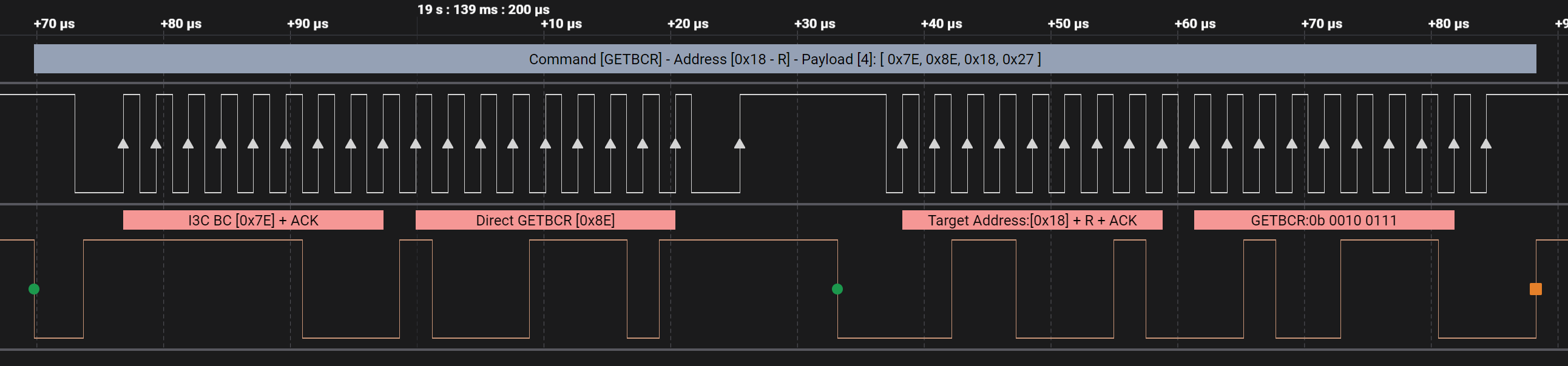
The screenshot above shows the direct GETBCR CCC sent to the ICM-42605 Target at address 0x18 and it's one-byte response of 0x27. Compared to the initialization, this is a very simple transaction. Overall, the waveforms generated by the Scout SC4420 look very nice. I haven't fully exercised it at low voltages yet, but operation at 1.8V and 3.3V has been solid.
Gotchas
Aside from the learning curve of figuring out how to string the commands together and providing the correct parameter values, there were a few other things that are worth pointing out:
(1) In I3C mode, the Scout SC4420 is only able to power the I3C bus at 1.2V, 1.8V, and 3.3V. For operation at any other voltage, the power will need to be provided by an external source and the SC4420 will need to be configured to use the external source for the voltage reference using the vio command.
(2) The supported clock frequency settings are fairly limited, and skew to the low-side of I3C operation. The only supported I3C clock frequencies are the following: 12.5MHz, 6.25MHz, 3.125MHz, 1MHz, 400kHz, 200kHz, and 100kHz. I would have liked to see more options between 6.25MHz and 12.5MHz as we work with a few relatively large I3C test buses that run happily at 8MHz, but due to the signal integrity issues of the long runs, cannot handle 12.5MHz operation. With such large step size, the SC4420 can't really be used to push I3C bus implementations to find out the max frequency they can handle reliably if they can't do the full 12.5MHz. Perhaps this is a bit atypical, but I suspect it's more common than not during early development.
(3) If you want to automate this device, be prepared to invest a fair amount of time into writing robust code that can parse it's output.
Summary
The Scout SC4420 is a diamond in the rough. It is sufficient at its job and is accurately marketed. Like most pieces of test equipment, there is little emphasis on the actual user experience, but it can be overcome by investing some time to learn how to work with it. Working with the SC4420 in many cases is preferable than the alternative option: writing code to implement an I3C controller on a microcontroller (either bitbanged or on an MCU with an I3C peripheral -- both of which would result in non-deterministic timings). I still long for more, yet given the current state of I3C dev tools / general industry-wide adoption, I think this device will certainly help move adoption forward and likely mature along the way as well.
Already working with I3C? Check out our I3C Basic Protocol Analyzer Plugin for Saleae Logic...


