// application note
AN0007 Interfacing an ams OSRAM time-of-flight sensor over I3C with the Binho Supernova
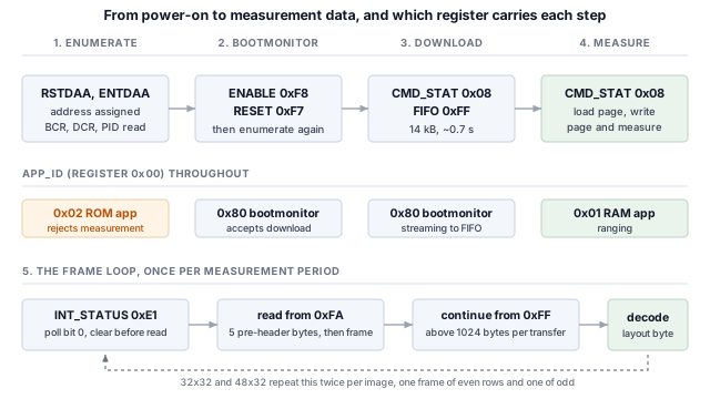
The ams OSRAM TMF8829 is a direct time-of-flight ranging sensor with a MIPI I3C interface alongside I2C and SPI. It reports a distance for each zone of a SPAD array rather than one distance for the field of view, up to 1536 zones per measurement, and it differs from a register-mapped sensor in three respects that determine how a host is written: its ranging firmware is downloaded over the bus at every power-up, results are returned through a FIFO rather than a register file, and a measurement is kilobytes rather than bytes. This application note shows how to bring one up from a Binho Supernova USB host adapter without writing any firmware. It covers enumeration and dynamic address assignment, forcing the bootloader and downloading the ranging application, selecting a zone configuration, the frame header field that determines the size of every zone, the transfer-length limit that a full-resolution frame exceeds, the row interleaving used by the two largest configurations, rendering the results, and an HDR-DDR frame transfer checked against the single data rate read of the same frame. The worked example uses the TMF8829 on a LIGHTRANGER 14 Click, and a reference Python utility that produced every output in this document is supplied.
- Products
- Binho Supernova
- Protocols
- I3C
- Topics
- Time-of-Flight Sensing
- Revision
- Rev 1.2 · September 9, 2026
// outcomes
What you'll walk away with
By the end of this document a reader with the hardware in front of them will have enumerated a TMF8829 onto an I3C bus, forced it into its bootloader, downloaded and started its ranging firmware, configured each of its zone grids, read and decoded measurement frames including the two configurations that arrive as two frames, rendered the results, transferred a frame in HDR-DDR and verified it against the single data rate read of the same frame, and established what the target implements from observable effects.
The part worked through is the TMF8829 on a LIGHTRANGER 14 Click. It is exercised on hardware and every output in this document is a real capture.
This note does not cover optical calibration, crosstalk compensation against a cover glass, the histogram output mode, or the point-cloud correction that converts per-zone distances into Cartesian coordinates. Those depend on the optical stack a design puts in front of the sensor and are documented by the sensor vendor.
// background
Background
The ams OSRAM TMF8829 is a direct time-of-flight ranging sensor with a MIPI I3C interface alongside I2C and SPI, on the same two pins. It measures distance by timing returned photons against an emitted laser pulse, across an array of single-photon avalanche diodes divided into zones, and reports a separate result for every zone rather than one distance for the field of view. The largest configuration reports 1536 zones, and each zone can report up to four returns at different distances.
I3C keeps the two-wire footprint and adds a substantial feature set on top of it.
Table: What I3C adds to a two-wire sensor interface
| Feature | What it gives a design |
|---|---|
| Dynamic address assignment | The controller hands out addresses at run time, so static address collisions stop being a board-design constraint and identical parts can share a bus |
| Identification from the bus | Every target reports a 48-bit provisional identifier, a device class and its bus capabilities, so a controller can enumerate a bus it was not built for |
| Common command codes | A standard command set, broadcast and direct, for enumeration, identification, configuration, interrupt control and reset, the same on every compliant target |
| In-band interrupts | The sensor interrupts the host on the data line, carrying a byte that says why, so no interrupt pin has to be routed or allocated |
| High data rate modes | Double data rate transfers move two bits per clock edge pair, doubling the signalling rate without raising the clock |
| Higher signalling rates | Push-pull clocking, to 12.5 MHz in single data rate mode, against the open-drain limits of I2C |
| Lower power | Push-pull signalling avoids the static pull-up current I2C spends continuously, and activity states let a controller tell targets what bus latency to expect so they can idle harder |
| Hot-join | A target powered up after the bus is running can ask to be enumerated |
| Standard reset and recovery | A defined target reset and defined error detection and recovery, rather than per-vendor sequences |
| I2C compatibility | Legacy I2C devices can share the bus |
A target implements the subset of that a sensor needs, and the subset differs between parts. This note works through a TMF8829 from a Binho Supernova USB host adapter: enumerating it, identifying it from the bus, entering its bootloader, downloading and starting its ranging firmware, selecting a zone configuration, reading and decoding measurement frames at every resolution the part offers, rendering the results, transferring a frame in HDR-DDR, and establishing which of the features above the target actually implements.
Three properties of this part determine how a host has to be written, and all three differ from a register-mapped sensor.
Table: What differs from a register-mapped sensor
| Property | Consequence for the host |
|---|---|
| The ranging firmware is not resident | The part powers up in a bootloader or a ROM application, neither of which ranges. The application is downloaded over the bus into RAM at every power-up, so it forms part of the boot time of any product built around the part |
| Results are returned through a FIFO | There is no distance register. A measurement is read as one contiguous transfer whose length is described by the frame itself, and a short read leaves the remainder in the FIFO to corrupt the next frame |
| A measurement is kilobytes, not bytes | A 48x32 configuration returns 4674 bytes per measurement at the smallest result format. Section 7.3 establishes the transfer limit this runs into and Section 11 gives the size of each configuration |
Nothing here requires a microcontroller, firmware, or a driver port. Every step is a command from a host PC.
// applicable devices
Applicable devices
The worked example uses a TMF8829 on a LIGHTRANGER 14 Click. The bus procedures apply to any I3C target; the bootloader, configuration and frame procedures apply to the TMF882x and TMF88xx family, which share the host interface described here.
// what's covered
What's covered in the note
- 01 Introduction
- 02 Required equipment and software
- 03 First contact: enumerate the bus
- 04 Application state and bootloader entry
- 05 Downloading the RAM application
- 06 Choosing a zone grid and starting a measurement
- 07 Reading a frame
- 08 Rendering a measurement
- 09 More than one object per zone
- 10 Declared capabilities against measured behaviour
- 11 Measured results
- 12 The utility
- 13 Practical notes
- 14 Troubleshooting
The full procedure, measured results, and reference code are in the PDF and the assets archive.
// materials
What you'll need
 Binho Supernova USB host adapter for I3C, I2C, SPI & UART View product
// our edge
We don't just follow the I3C spec.
We don't watch from the sidelines. Plugfest after plugfest, our team is in the room where vendor I3C implementations come together — finding edge cases, debugging quirks, and validating real silicon against the spec.
// track record
We've been doing this for years.
Long enough to know where the gotchas live.

// 01 · standards
We help write the spec.
Binho is a MIPI Alliance Contributor Member, actively shaping I3C — a foundational protocol for cutting-edge embedded systems.
// 02 · tools
We build the tools.
200+ semiconductor companies use Binho tools to develop, validate, and ship devices with I3C protocol support.
// 03 · plugfests
We prove it in the field.
We've verified our tools at the past 5 MIPI I3C Plugfests — and helped others verify theirs too.
// trusted by engineering teams at


+ hundreds more
// related notes
Related Application Notes
// newsletter
Get new application notes
New notes, firmware releases, and tool updates from Binho. No spam, unsubscribe anytime.
Put it on the bench
Every step in AN0007 was run on the Binho Supernova. Get the hardware to reproduce it, or talk to our engineers about your I3C bring-up.